kenwood ts-570 DSS repair

so this was the first repair to clue me in to the ceramic package cold solder issue.  i had been chasing a “bump its fixed” bad receive issue.  every so often the SSB receive would drop down to no S meter reading and barely audible for even nearby 20 over signals.  a good bump would fix it for ahile, then it would drop out again.  after opening the case, resoldering any suspicious joints in the area, closing back up maybe two dozen times, i finally removed the shield over the DDS unit.  pressing on the PCB around it seemed to have the greatest effect on the cutout.

ts-570dsssch

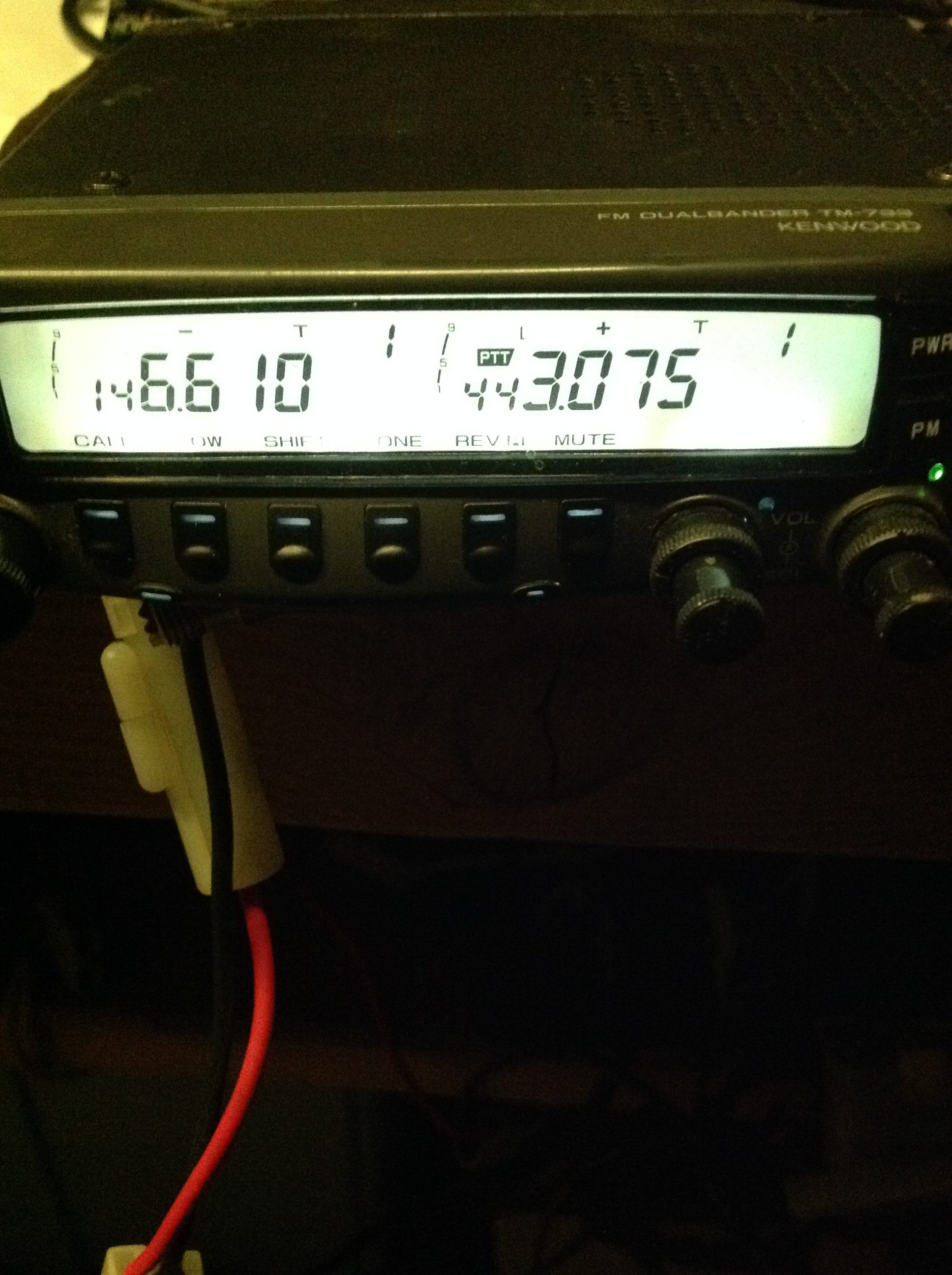
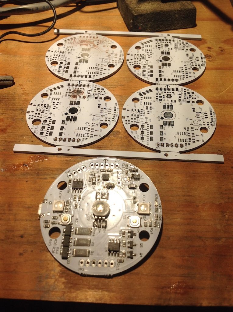
thiere are two direct digital synthesiser units in the ts-570. they consist of an extinct custom chip F71022 and two ceramic pack precision resistor ladders.  they are ic501 and 502 are the DDS, and CP500 CP501 CP502 CP503 are the four packs.  my guess, the ceramic packs are only side soldered and heat expansion delta from the epoxy PCB cracks the joints.   normally surface mount components do not get cold solder issues, its the hand soldered bigger parts and jacks usually.  but these are like  little ceramic circuit boards on top of the regular epoxy board and they dont stretch and contract the same. i reflowed cp500 and 501 that go with ic501 which gens the 8.83mhz carrier to the mixer and that cleaned it right up.  pushing on the pcb no longer cut the SSB.  these ceramic packs are in bunches of kenwood radios from 80’s onwards as they are very precision and probably temp stable too.  tm-733 uses one for PL tone generator, ts-950sdx has same double DDS chips same packs, etc.

image

ts-570dsspcb

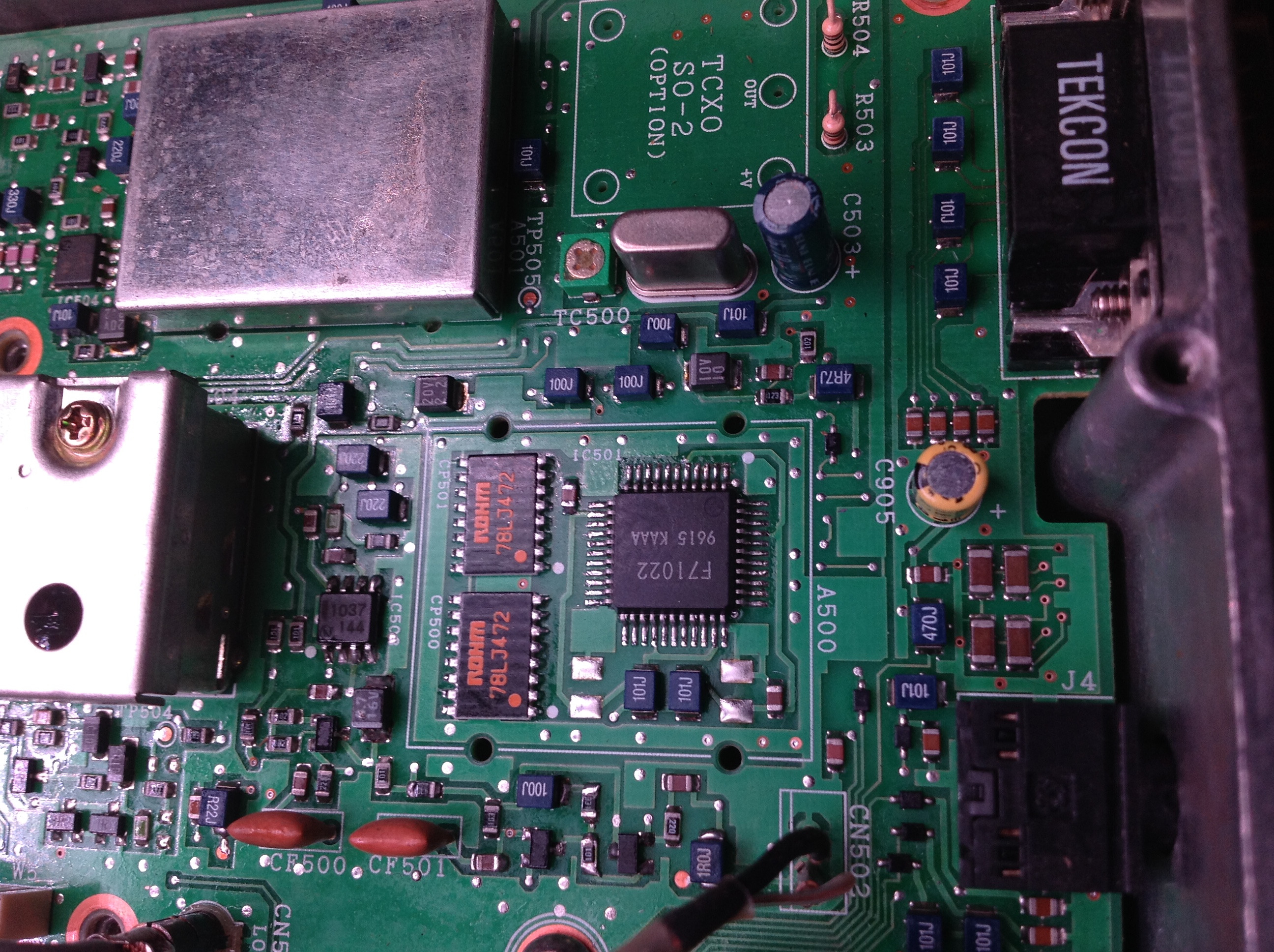
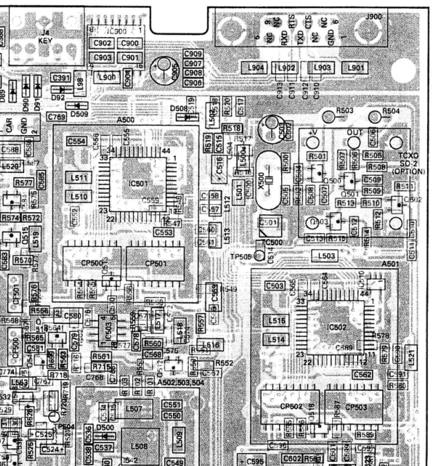
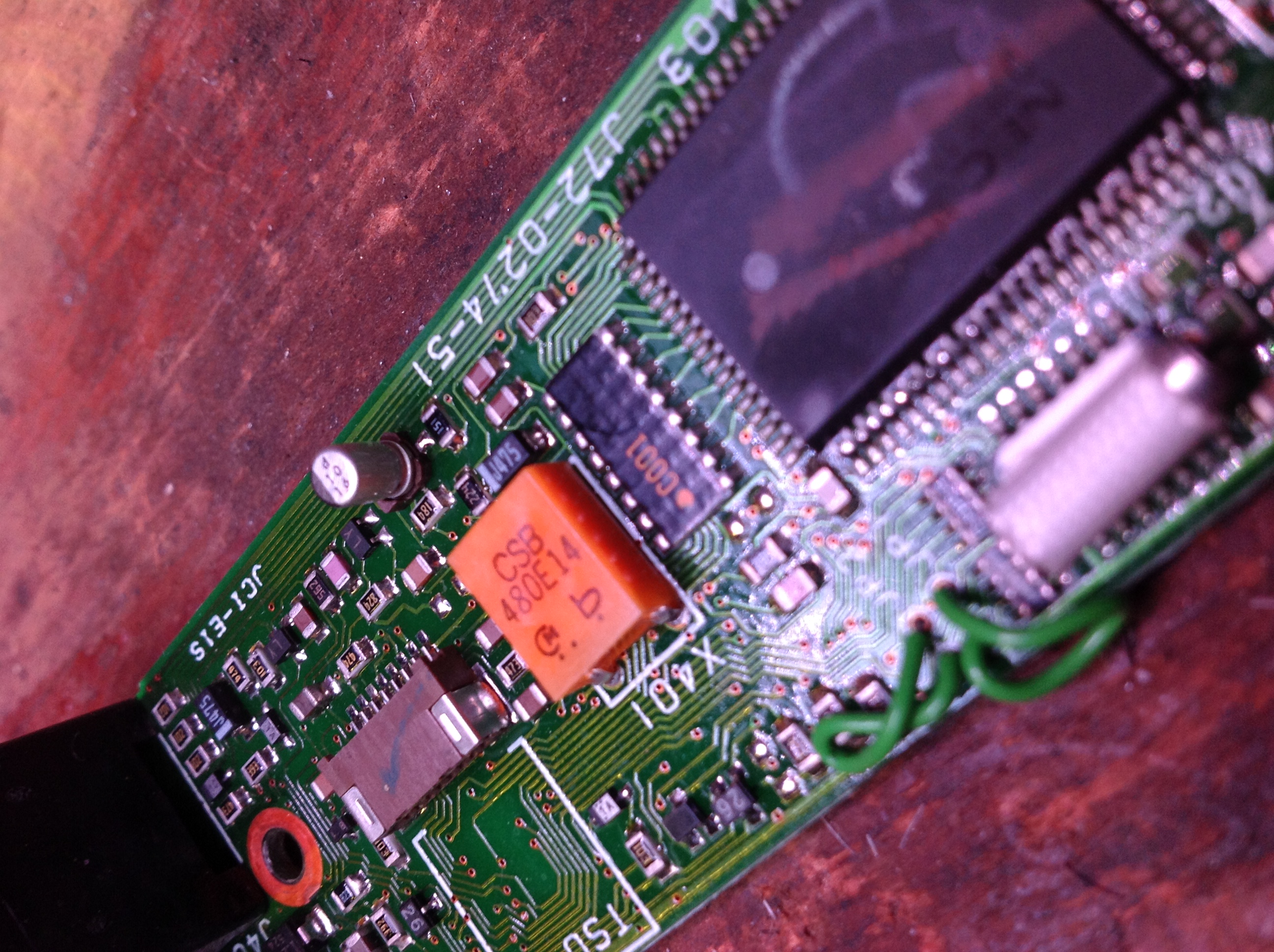
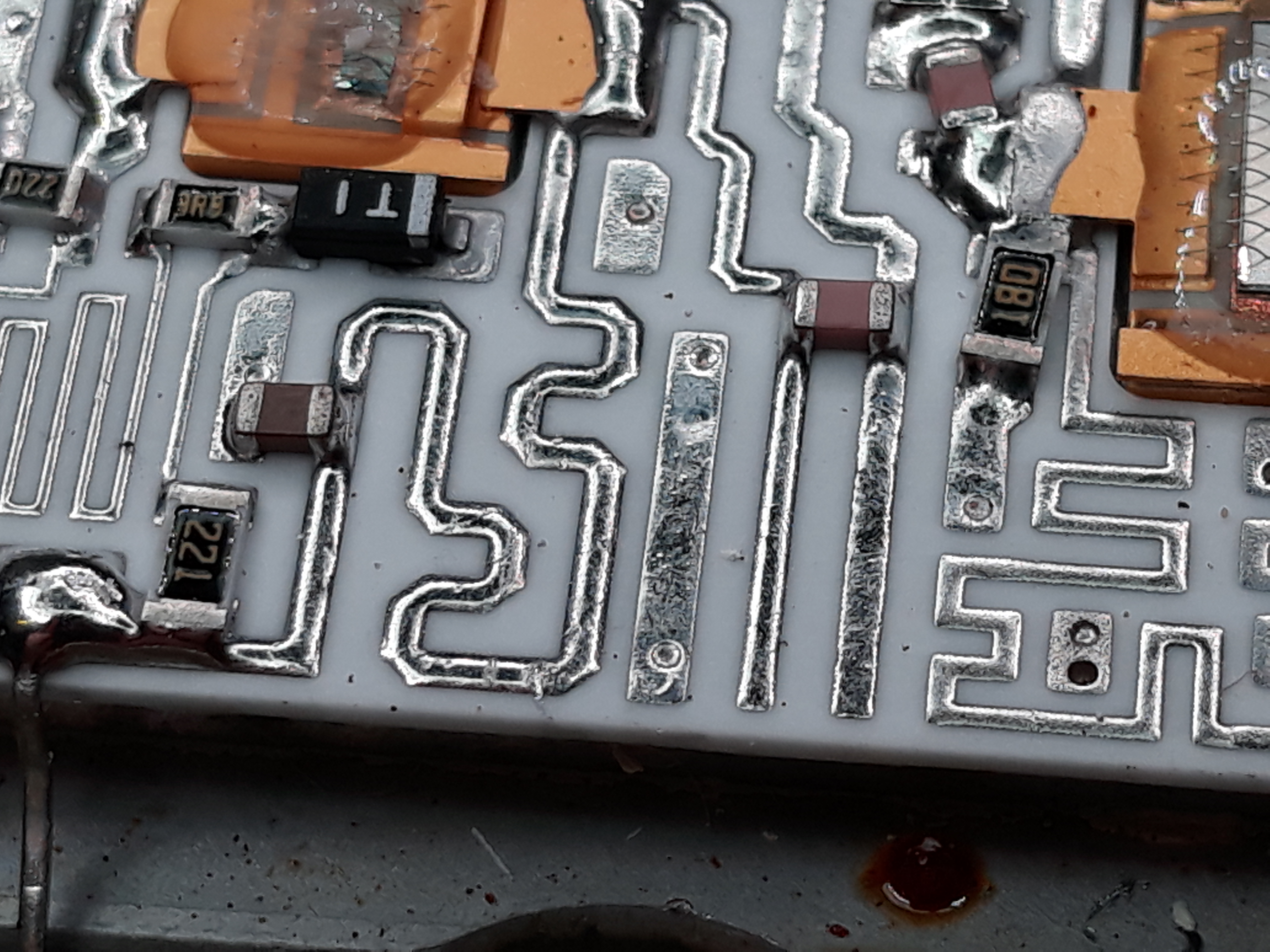
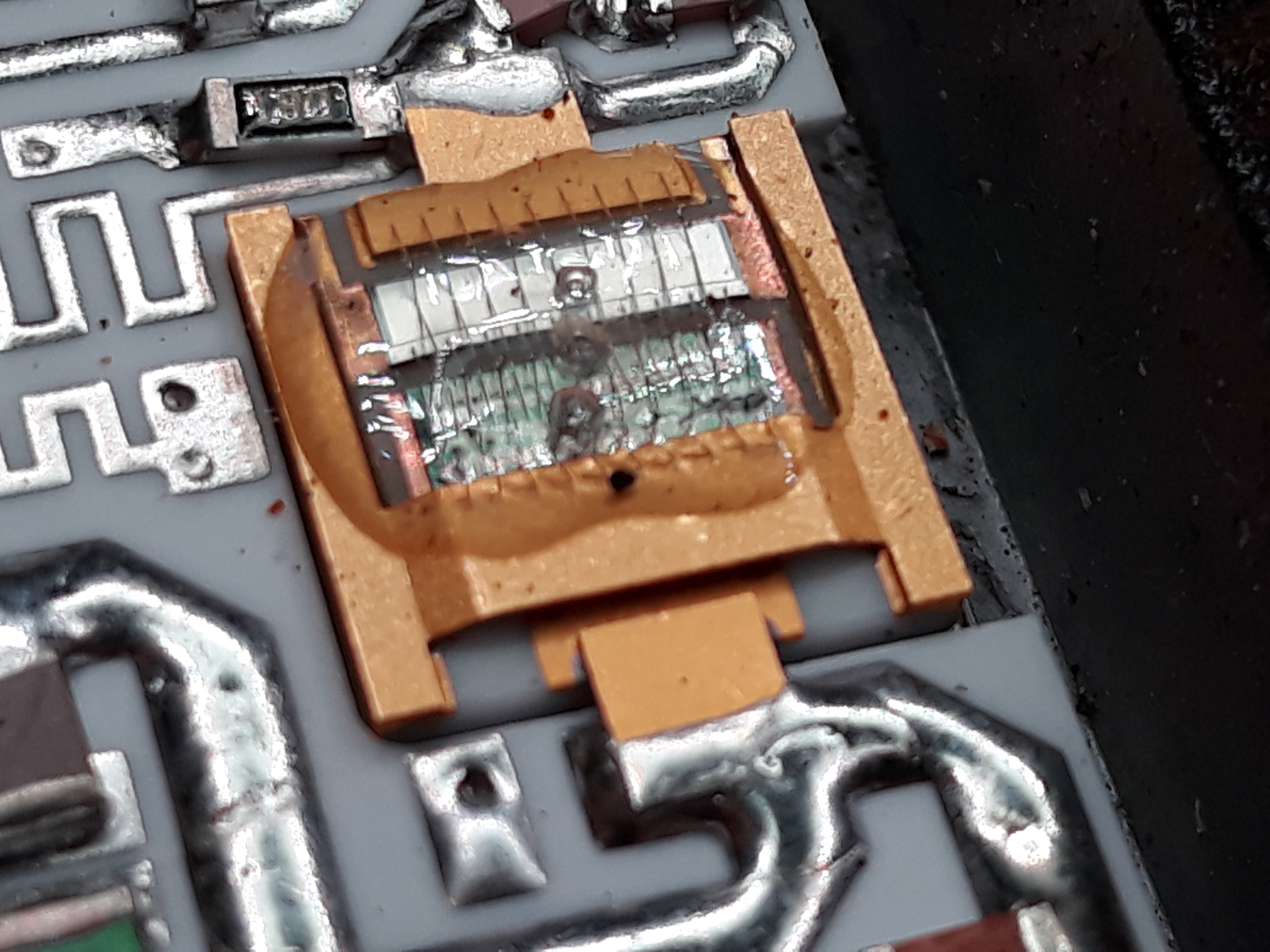
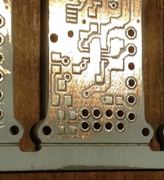
i know not best pic, but here is the dds unit w shield off.  other dds is top left still under metal,shield.  here looking at tx/rx board, serial jack top right, dds is big square chip in middle, and the resistor packs are to the left of the DDS with red lettering.  i used a 1/64″ tip soldering iron, smeared flux on both sides of the packs, no solder, just touched each “notch” on the sides that is the contacts.  no real legs or leads, just conductive paint goes from top of pack over the side edge.  not sure if it continues under the pack.  carefull not to scrape this paint off, and go in hot and fast and get out cuz the ceramic sucks

kenwood tm-733 fixes

i post these in the hopes someone having similar problems will find these notes and will help them in some small way get their gear on the air again.

i was all excited about repairing the backlights on my new-to-me Kenwood TM-733 so put it on the air, and things looked good.  then i turned on the CTCSS aka PL Tone and the transmitted audio got all garbled and bad distorted.  Looking thru the schematic i find the same type of precision resistor pack i just re-flowed to fix a TS-570 is the heart of the PL tone generation circuit.  sure enough, re-flowing the CP401 resistor pack and clean PL tones are output again.  the r-pack is between the orange xtal and the large CPU.  contacts are more on the side than on the bottom, 25 years of heat cycling and the ceramic moves not same as pcb.

image

so that fixed the distorted PL tones enough to hit the local repeater.  good friends tell you the truth, so back on the bench after Ken gracefully told me “sounds like crap”.  checking power output and meter doesnt move at any power setting.  hmm, its obviously modulating and PL is clean enough to hit the local repeater?  check on google about the final amplifier chip turns out, its not a chip, its a module.  wut? i thought these things where epoxied inside?

20200325_220825

nope, module, and the plastic cover pops right off to expose the main drive transistor, its pre-drive transistor, and a simple amplifier power chokes and feeds.

20200325_220911

can you see the hairline crack in the choke line just off the tip of the probe?

image

no? neither can i.  but the meter can see it probing from either side no contact.  right in the middle of the bottom curvy trace (which would make a fun racetrack if i where an electron thus the inductance)

20200325_221108

so some sloppy solder dragging and we have contact again.  i say sloppy cuz the ceramic substrate ate the heat as i applied it and the solder kinda stayed right at the eutectic point.  nope, no pic, im bareassed.   but that fixed it, full 50w output and sounds clean so far.   gonna have to get a proper service monitor or gen/spectrum unit all these radio projects….

20200325_221135

heres a closer look at the 60 watt drive transistor.  looks like an epoxy blob with a metal wire screen over perhaps a dozen small dies wired in parallel?

25 year old TM-733 radio gets new light

so the little 6volt lightbulbs on this awesome Kenwood TM-733radio burned out.  made it 27 years ao thats pretty good.  soldered in some white 3mm LEDS and changed the series resistors, boom, more readable than the orgiinal and way less current draw.  next one ill try warm white, i kinda miss the warm glow of the original even if this has netter contrast.

image

image

two more working designs

more a re-design than a scratch design, but still had to push the same amount of pixels and solder.  you’ll see these on the market soon, till then here’s the “factory proofs” with some double-check their Q with my A.

hella bright blinky disks.

IMG_0737

ultra cool glow sticks,

IMG_0741

and sometimes ya just gotta check how good they printed by removing the top screen print to expose the copper traces.  modern SMD parts are sooooo damn tiny in sub-milimeter kinda tiny.

IMG_0743


Vintage Brakes

so these are called Warner electric brakes, designed by the guy who designed magnetic speedometers standard in pre-computer automobiles.  clever design, but i think the standard modern setup is in the plans.

here’s the hub off, friction pads inside the hub, and magnetic coil is the ring around the spindle.

20170517_172330.jpg

closer look at the hub pads,

20170517_172337.jpg

i assume it works like: give coil juice, it gets torqued by pulling these pads to it and then the doughnut is forced to turn a little bit.  that turn then pushes on the pad ring to engage the hub.  heres a closeup of the tab that sticks out of the coil ring where it can push on the ring on either side (forward or backward same power).

20170517_172345.jpg

so yeah, i’m back to the wordpress blog thing, which copies automatic to fbook.


more battery lies

ok, these are HP batteries.  one is as expected, full of cells.

img_0399

but the other has these black cells, ive never seen black cells before?

img_0396

oh wait, those are not cells, those are hollow plastic spacer tubes?

img_0397

i guess even the big buys cut corners when they can?

would never tell from the outside that 1/3 of the cells are missing inside?

img_0395

img_0398


hollow promises

original apple macbook batteries are a study in density packaging, not a spare cubic in there, all pouch cell and fancy TexasInstruments BQ battery chip.

img_0374

was going thru some dead batteries, and found one non-original that felt suspiciously lighter than any others.  you don’t own it till you open it, so,

img_0376

looks all official on the bottom, CE cert and all that, but, what’s missing inside? how about only 1/3 the space is battery cells?

img_0375

and what kind of cells are these?  look like some sort of tablet battery, really thin, testing one now shows about 2800mah capacity, WAY lower than what the outside says!

img_0379

yup, even says only 13.87Wh, way less than the 57Wh the outside says!


img_0377

at least it looks to have a cell balancer, and since it talks to an apple laptop, must have the original TI chip right?

img_0378

nope, atmel atmega16, might explain the weird responses from the SMC queries….


ebike part 3

last runs blew out the low volt cutoff, so i added a fancy digital VA meter.

img_0336

here’s the 400 amp shunt added to the pack negative.

img_0348

and the whole guts on the bench for testing, fancy meter, 400 amp speed controller, 200 amp cutoff solenoid, and even the new throttle control.

img_0345

fun first, art second, safety third, how about 250 amp inline fuse on the fly?

img_0354

all tucked back into the battery box plenty of room for the charge balancer board and a beer or two.

img_0359

and then stick it all back on the bike.

img_0358

nice blue LED display, unless use an ipad to take the pic…


Amp game too strong

well, i sent the new ebike pack out, as the new charge balance board was doing ok.

IMG_0069

so they ran it hard, i mean really hard, charged it up fine, then ran it even harder still, till the smoke came out.  i don’t know if you’ve ever seen lithium battery fires, youtube can show you, these cells have the equivalent of a few dozen laptops together, so the fire hazard was very real.

lucky, it was just the huge cutoff transistors that melted away.  they must have not been fully “on” with my tap to the balancer board, as the fuses did not blow rated 250amps.

IMG_0072

gonna be hard to remove them from the heat sink.

IMG_0073

never seen inside one of these before.

IMG_0074

now i know how the terminals work, can see the rest of them still attached to the PCB.  i think i’ll do a breaker and shunt instead, a smart display and current monitor, and use the big contactor on the bike as the cutoff.

stay tuned…